Frame torsion testing underway

69427

The Artist formerly known as Turbo84
Joined
Mar 30, 2008
Messages
2,972
Location
Clinging to my guns and religion in KCMO.
A few of you might remember some frame modeling I did a while back to try some ideas I was kicking around to stiffen up the spare '69 frame of mine.
IM000853.jpg

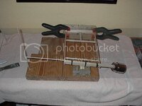
Got most of the frame tweaks done, and am spending some time twisting the frame looking for areas I missed. So far it's pretty amusing, but I'm warping the crap out of my anchor point (my car hoist), which is gumming up my measurements. I'm trying to look at this positively, as the frame does appear to be transferring the torque from the front moment arm back to the lift anchor area. I'm doing a couple changes to the anchor area trying to stiffen up that part of the lift runner. I've got the rear of the frame clamped (by the batwing mounts) to the lift runner, and using the car weight to help keep things from moving around. (Plus, I didn't want to have to push the car in and out of the garage.)
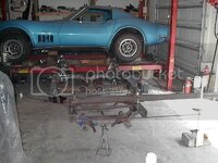
IM000966.jpg

I'm using a seven foot moment arm, mainly because I can't close the garage door if I use anything longer. With my weight, and the weight of the arm, I'm putting 1500 lb-ft of torque on the frame during these initial tests. Once I get the anchor area stabilized, I'll hang some additional weight on the arm to try to get to 2000 lb-ft. It's hard to see in the picture, but I'm using another small arm and a yardstick to make the deflection measurements, and then will have to blow off the cobwebs from what I learned in 8th grade geometry to calculate the angles and such.
 
I remember that frame discussion,
I still wonder if the engine was on a fixed plate rear or front of the engine if it would reduce the torsion.

I'm building a moderate cam/compression ZL1 for it. Using the (aluminum)block in a torsional mode just scares me a bit. LOL
I'm still mulling over what additional structure I can add in the engine/trans area.
 
I'm building a moderate cam/compression ZL1 for it. Using the (aluminum)block in a torsional mode just scares me a bit. LOL
I'm still mulling over what additional structure I can add in the engine/trans area.

Ok I forgot about that.
I would be scare to test this too.
I like that tube but I have a question, Is it removable so you could get the trans out from under the frame?
 
Last edited:
Do you have a stock frame to benchmark improvement? Sure would be nice to see a comparison.
 
.............
I like that tube but I have a question, Is it removable so you could get the trans out from under the frame?

The torsion tube bolts in. (Last thing after the driveshaft is installed.) I cut open the front center area of the pinion crossmember and welded some nuts inside, and then reinforced that area so it could transmit the torque to&from the tube. The trans crossmember also has a reinforced area where the tube bolts to it. The two crossmembers act as moment arms on each end of the tube.
 
Frame front pivot methods: Same results?

I've been doing some initial twisting on the frame (along with multiple improvements to the carlift anchor area to reduce the distortion and resulting error angle numbers I have to factor out), and I've got a question. I've been twisting the frame around a fulcrum point under the center of the front crossmember. I saw a picture of Herb Adams in his book doing some torsion testing, and he was using one of the lower A-arm attachment points as the pivot point. We're both measuring the twist angle of the front crossmember, but I'm trying to make sure that we get the same results with these two different pivot points. I just need some fresh perspectives and opinions on this. I appreciate any clear thoughts on this.

thanks,
Mike
 
The mistake that is commonly made in chassis dynamics is the assumption the forces are applied axi-symmetrically through the longitudinal axis of the car (complicated way of saying through the center-line). Chassis torsional forces are related to, but not necessarily, cornering forces. Forces applied to the frame in the real world are through the suspension pickup points so the twisting force axis could be left rear to right front (for example).

With your setup, you have to bridge the front pick up points with your beam and the fixed end. Now that beam becomes a structural element between the L and R pick up points. This only measures twist, not a real world conditions.

With all that said, what you are doing is the best known test of stiffness for a vehicle's structure. All you see in trade pubs is bending stiffness and torsional stiffness (in degrees).

So the Herb Adams setup is probably more realistic but only slightly.
 
The mistake that is commonly made in chassis dynamics is the assumption the forces are applied axi-symmetrically through the longitudinal axis of the car (complicated way of saying through the center-line). Chassis torsional forces are related to, but not necessarily, cornering forces. Forces applied to the frame in the real world are through the suspension pickup points so the twisting force axis could be left rear to right front (for example). I agree. I'm frequently cutting the apex a bit close, and end up running one of the front wheels over the apex curbing, putting some diagonal input into the chassis. With your setup, you have to bridge the front pick up points with your beam and the fixed end. Now that beam becomes a structural element between the L and R pick up points. This only measures twist, not a real world conditions. The beam is currently bolted to the front frame rails above the front crossmember. I'm not terribly concerned about it being a structural mmber as the front crossmember is pretty beefy, and the beam somewhat floats on the downward side. It actively pulls up on one side, but merely pushes down on the other.
With all that said, what you are doing is the best known test of stiffness for a vehicle's structure. All you see in trade pubs is bending stiffness and torsional stiffness (in degrees).

So the Herb Adams setup is probably more realistic but only slightly.

That's what has me a bit perplexed. Adams' test forces one (front) corner down (by his body weight at the end of a long moment arm), while the other front corner is bolted to an anchor pivot. In the real world, it is easier (if not possibly the only way) to get the frame to bend substantially by forcing an upward motion on the frame by the action of the corner suspension hitting a bump or apex curb. While the frame distortions are in opposite directions, perhaps the curb input force, and Adams' input force, both yield the same answer.
I'm just trying to make sure I'm not doing anything stupid here. It's a PITA to keep attaching/removing the moment arm (due to its weight) to get the measurements zero'd, and placing the dial indicators around in such a way as to be readable from my vantage point balancing on the end of the beam. The theory of these measurements is relatively simple. The execution of it is just tedious.
 
I would put a laser level at the rear suspension, mid chassis and front and measure the twist in degrees. that what you really want to know and will keep you from trying to read indicators.


.
 
I would put a laser level at the rear suspension, mid chassis and front and measure the twist in degrees. that what you really want to know and will keep you from trying to read indicators.


.

I've got a couple laser levels I've been using to give me a visual indication if and when something is moving or bending (that's how I first noticed my anchor setup wasn't as immovable as I had hoped). They are only equipped with level bubbles, so there's no real info there. And, given that most of the frame is only twisting in the partial degree range with my 2000 lb-ft load, any angle meter would have to have resolution in the tenths or hundredths of a degree in this case.
Outside of a high dollar level, I'm not sure I have any options but continuing to use my dial indicators on this setup.
 
Not a bubble level, a laser level. The kind that shoot a beam. You could easily measure tenths of degrees if you projected the beam on a wall 8 or 10 feet away and it looks like you have that much space. Same way wheel alignment works.
 
Not a bubble level, a laser level. The kind that shoot a beam. You could easily measure tenths of degrees if you projected the beam on a wall 8 or 10 feet away and it looks like you have that much space. Same way wheel alignment works.

These are laser levels. I've been aiming them at the walls and my toolbox to give me an indication of when things are moving. My reluctance/uncertainty so far has been when trying to determine if the beam changed location due to the laser being rotated (due to twist) or being elevated. Unless the laser is exactly placed in the centerline of the rotation, I worry about the beam being displaced due to distortion of the mounting point. Essentially, I'm just concerned about errors due to height changes rather than angle changes.
 
Top