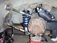
finally working on trailing links and toe rod for rear

daveL82

Well-known member
Joined
Apr 10, 2008
Messages
231
Well I haven't done much with the vette for several months as I've been doing a few track days on motorcycles and working on our place in Arkansas which is about 5 hrs from Dallas TX. The only time I can work on the property is every other weekend.

Today I pulled the coilovers, caliper, and managed to get the T-arm shims out of one side of the arm (doing one arm at a time). My sawzall is in AR so I'll have to retrieve that to cut the bolt and other shims out by the look of it.

Plan is to use some of Marcks work along with some ideas from the Greenwood suspension. I previously fitted coil overs to the rear and added brackets to the strut rod bracket for a lower toe rod in parallel with the lower strut rod. Thought about an upper link lke the greenwood but wasn't sure I could locate the inner mounting point properly.

It'll be a slow project but it's a start.
 
Last edited:
It's gotta be tough working on stuff when your 5hrs away. I have a hard enough time and everything is right here!
 
BB - The vette is in Dallas with me but the sawzall is in AR as I was using for work on a shed. Although I wish the vette was up there as I have a new barn with a concrete floor and lots of room. I'm crowded with the vette in the garage.
 
Started to cut the drivers side T-arm out today and what a pain but should have it out tomorrow. I've decided to go with an upper toe link parallel to the drive shaft as this allows me to add minimal material to the bearing carrier for an upper mount therefore reducing unsprung weight.

Will work on the two trailing links once the T-arm is out.
 
Dave, are you doing it the greenwood way? links behind half shafts?

You can drill and tap your diff carrier for M12 bolts (or UN sizes of course) and mount the bracket off the bosses. I did that, never completed it though.

Anyway, it's EASIER to do it the guldstrand way. It's a little less precise than the greenwood setup but it's a marginal difference and it's impossible to screw up. The lower camber rods control toe between the individual settings of the front vs. rear one. You can not screw up their placement. just put them a good distance apart so you have some fine tuning over a good amount of turns of the sleeves.

If you do it the greenwood way you have to properly position the inner mounts, directly behind and in the same plane as the inner u joints. The outer one goes in the same location as the outer joint, then you have to have the rod & halfshaft parallel from birdseye view too. Small alterations in the outer pivot position can alter your toe curve on bump/jounce (a little toe in on bump may be helpful) but if you screw up the placement you might experience weird handing issues.

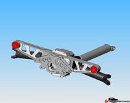
Here's how I did the batwing:
24874d0f68217e.jpg

This was more or less how I was going to do the bracket. Might be a little overkill, single shear would most likely be fine.
You can also mount the inner rod end perpendicular to the bracket, the suspension won't swing up/down far enough to cause binding anyway.

24874d14eb1082.jpg
 
Marck - I was thinking along the lines of the greenwood setup using the upper link so that I minimize the mount of addtional metal I need to add to the bearing carrier (upper mount means less addtional structure).

I agree with the need to match up the inner top mount with the drive shaft inner joint center.

However before I get to the mounts I need to finish cutting out the old T-arms which is a slow and hot job in this Texas heat.
 
After much effort and cussing I was able to get the drivers side T-arm out. As my good saw was at our place in AR my friend let me borrow his which I proceeed to wear out as it was cheap HF piece of junk. Yesterday I broke down and bought a DeWalt saw to finish the job so when I'm done I'll give him the saw.

Pulled the wheel off the passenger side and found the caliper leaking so I'll replace the rears with Wilwoods as I did in the front. Enough of these stock POS.

Next week I'll begin fabricating the front backets for the trailing arm links
 
I believe I used forged superlites in the front (4 piston). I need to confirm this but need to pull the wheel to check as I did the conversion 2 years ago and can't remember. Also need to make sure I match the piston diameter up front and rear.
 
Will I got back to the vette last week and made some good progress.

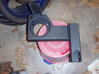
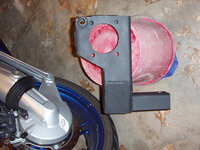
Cut off two 11 inch lengths of 2x6 square tubing and cut the 3 1/8 inch hole for the spindle mount and 4 1/2 inch hole for u-joint flange clearance. The extra length of the tubing gives me a place to weld on and addtional lower link for toe and still use my rear mounted coil overs. Using a 4 1/2 inch hole saw on a drill press was scary and produced a lot of noise but got the job done

I still haven't decided on trying to make the trailing links as long as possible (just rear of the spindle centerline) or take the easy route and anchor them in front of the spindle.

Once I have every thing located and tacked in place I'll remove extra metal from the rectalular tubing to save a bit of weight.

Any one got a template for mounting Willwoods to the rear?
 
OK I have the 2x6 section section cut. I put in the two holes mentioned above so the cast spindle bracket is centered and the other side has clearance for the u-joint. The 2x6 section is 11 inches long and at the rear I've welded a 2x2 tube verticle which give me the lower pivot point for the parallel lower toe link. The verticle tube also doubles as a mounting point for the rear mounted coil-overs. The verticle tube is 8.5 inchs long and is notched so the lower pivot is inline with the spindle mount. I'll try to post pics this weekend.

I have a couple of questions for Marck:

Will have the coil-over at the rear put excessive load on the trailing links?

Try to make the trailing links as long as possible but the 80 diff mounts stops me from moving the upper link mount further back. Other solution?

When at ride height do your trailing links point down towards the frame mount?

dave
 
When at ride height do your trailing links point down towards the frame mount?

dave

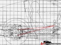
Dave, This is a C4 diagram but it may be useful for your project. It looks like the trailing links point to a center that is up. I suppose you have to consider the jacking effect in a C3 adaptation but you are probably on the right track with the longer arms.

448c9acb7aed90.jpg
 
When at ride height do your trailing links point down towards the frame mount?


This is a problem with lowered F-bodies, once lowered the rear control arms point downwards towards the front. I installed relocation brackets and lowered the rear mounting points so that the arms point upwards towards the front. It made a big difference. I would think the same applies to our C3s.
 
I was originally hoping to put the rear arm location points to the rear of the drive shaft. However when I do this the top arm is riased to a point that makes it difficult to located the front pivot point on the frame as it would be a bove the current frame pocket.

I supposed I could go back to the original greenwood design that used shorter arms that attach in front of the drive shaft
 
We'll I was beginning to wonder if I'd ever get to the point of posting pics of any significant progress. These last few weeks I put a lot of focus back on the vette and got a lot done. I still need to get the correct bolt lengths in a few places, set the wheel base and caster which will confirm the correct trailing link lengths, work on the upper shock mount etc...

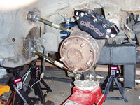
The hub carrier is made and in place along with the Wilwood mounting brackets. I left the rotor off to give a better view.

484630743_KQmHd-M.jpg

Another view and you can see the arm at the rear attaches to the rear toe link which runs parallel to the strut rod.

484630730_8qmbz-M.jpg

A view of the hub carrier for the passenger side. The bump stop bracket has yet to be shortened.

484630763_WfMww-M.jpg

Another view of the hub carrier

484630750_V6hk6-M.jpg
 
Last edited:
I assume the rear bracket is for toe control? How are you doing the center mount? Looks like you already have a toe control rod in place in the top pic?
 
Marck, yeah rear downway bracket is for rear toe link.

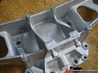
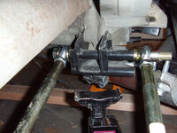
I modified the center bracket to remove the struct rod offset normally found on the 80 to 82 diffs and added the mounting point for the rear toe link. Basically cut tubing that has clearnace for 5/8, drilled the bracket, welded the tube to the bracket and then added extra material to the bracket to reinforce the tube. I can now run one bolt through the tube for the front and rear heim joints.

I added two tubes to the center bracket. one is stock location and one lower to remove camber if I ever need to.
 
Marck, I was able to get a pic of the center bracket tonight.

I also have a bar that connects from the left side to the right side of the bracket. it goes between the rear most rod ends and the nut. Did this to distribute the load at the end of the bolt.

Each section of tube has a triangle bracket to reinforce it.

485376888_dUADC-M.jpg
 
Top